![]() There were significant changes made to VLAN configuration between OpenWrt 19.x and 21.x. Also, many of the target chipset were migrated from swconfig to DSA (Distributed Switch Architecture), which introduced differences in bridging.
There were significant changes made to VLAN configuration between OpenWrt 19.x and 21.x. Also, many of the target chipset were migrated from swconfig to DSA (Distributed Switch Architecture), which introduced differences in bridging.
In this article, I will create a set of VLAN for my OpenWrt 21.x DSA-enabled router with isolated guest Wi-Fi networks.
I will be following the instructions laid out by OneMarcFifty, who has created a set of excellent youtube videos on VLAN and firewall configuration. All attribution of credit goes to him, I am writing this up only to provide additional details.
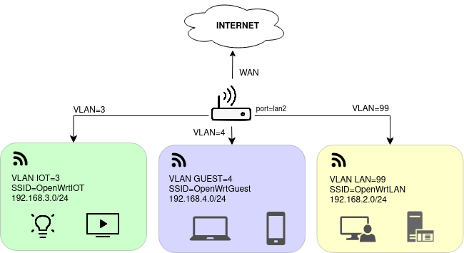
As illustrated in the diagram above, we will create three VLANs: IOT, GUEST, and LAN. Each will have its own network CIDR block and Wi-Fi connection.
- LAN = VLAN 99
- Can reach public internet
- Can manage connected devices in IOT network
- IOT = VLAN 3
- CANNOT reach public internet (no ‘spying’ or phone-home for IOT devices)
- Cannot reach devices in any other network
- GUEST = VLAN4
- Can reach public internet
- Cannot reach devices in any other network
Here is OneMarcFifty describing these same VLAN requirements.
Overview
Here are the high-level steps we will take to implement this design:
- Inspect initial state
- Create VLANs and have LAN interface use untagged VLAN 99
- Enable bridge VLAN filtering on device ‘br-lan’
- create VLAN 3 (IOT)
- create VLAN 4 (GUEST)
- create VLAN 99 (LAN)
- Configure tagging
- Modify LAN interface from using ‘br-lan’ to untagged VLAN ‘br-lan.99’
- Enable bridge VLAN filtering on device ‘br-lan’
- Add interfaces for IOT and GUEST VLAN
- Add Firewall zones
- Add GuestZone and IOTZone
- Allow LAN users to reach IOTZone
- Add exceptions for DNS and DHCP requests
- Set firewalls zones on network interfaces
- Add Wi-Fi interfaces for each network
- Setup OpenWrtLAN wireless interface
- Setup OpenWrtIOT wireless interface
- Setup OpenWrtGuest wireless interface
- Enable all wireless interfaces
- Smoke Test Scenarios
Inspect initial state
First, let’s look at the initial state of your OpenWrt 21.x router. This will differ slightly based on your chipset and router, and may have vestiges from older versions if your system was upgraded (and configs were migrated).
For this article, we have our OpenWrt router LAN at 192.168.2.1 (default from factory would be 192.168.1.1), with its upstream WAN interface on the 192.168.1.0/24 network.
If you want to set the LAN of your OpenWrt router to the 192.168.2.0/24 CIDR block to match, the command below will change it.
sed -i 's/192.168.1.1/192.168.2.1/' /etc/config/network
reboot -d 0
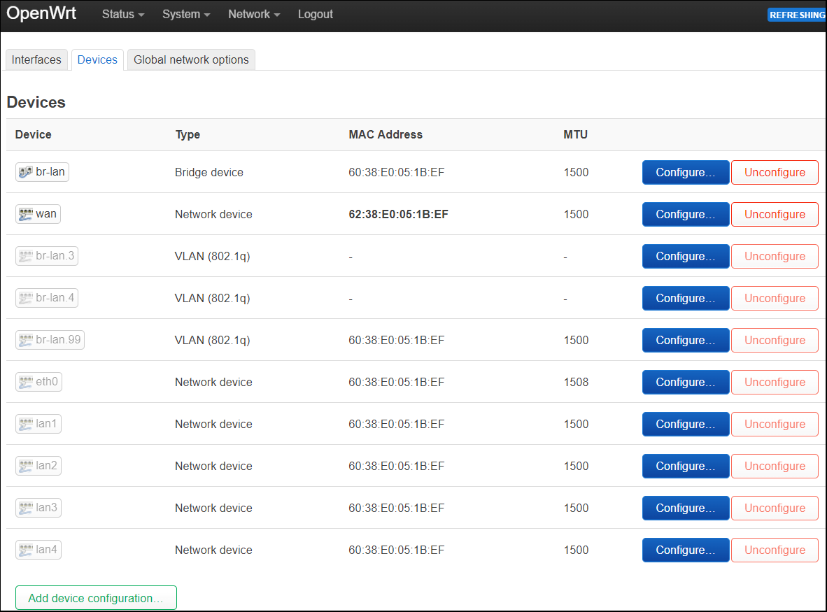
Devices
On a chipset that supports DSA, a fresh install will show a bridged ‘br-lan’ and then ‘wan’ device. Each port of the switch is shown as a grayed-out network device (eth0, lan1, lan2, lanX).
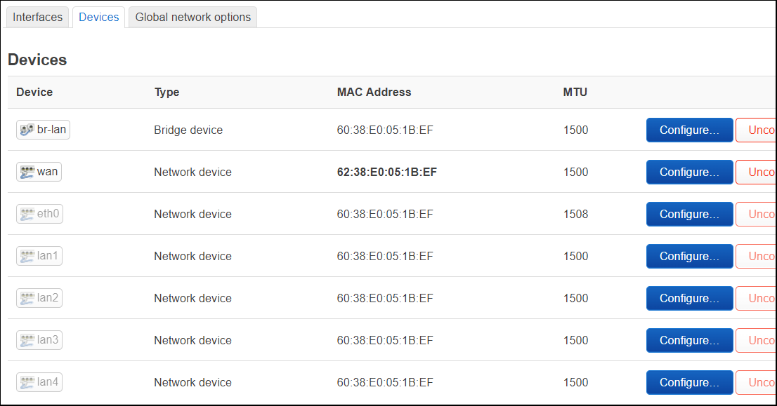
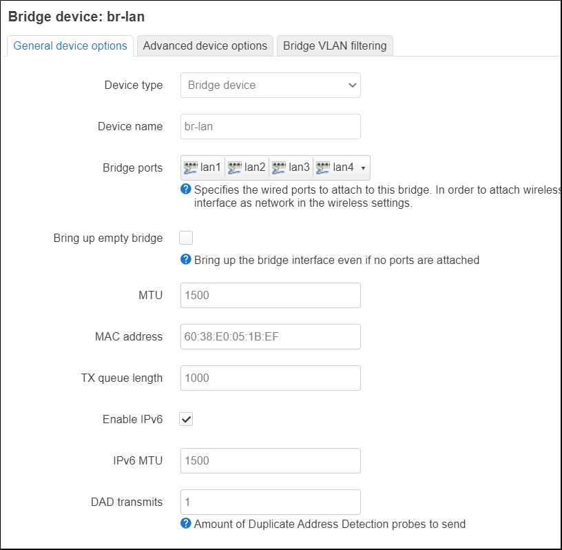
The ‘br-lan’ device is a bridge for all the ‘lanX’ ports.
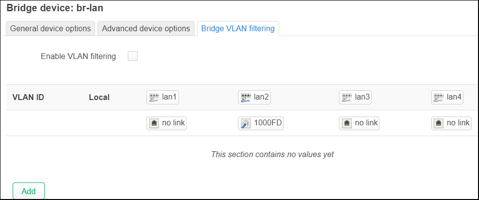
And the bridge VLAN filter is currently disabled.
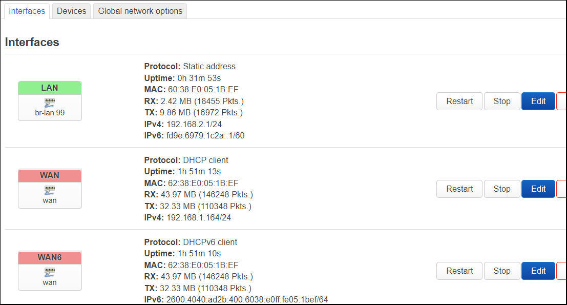
Interfaces
On the interfaces page of a fresh install, you will see a LAN, WAN, and WAN6 interface.
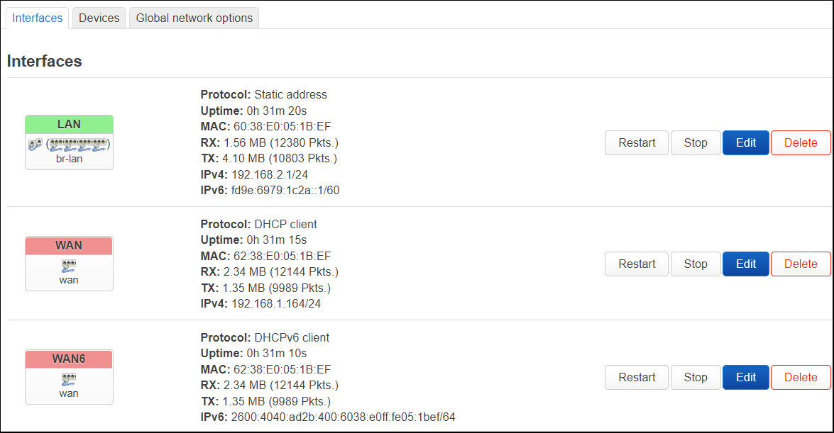
The LAN uses ‘br-lan’ as the backing device.

System configurations
From either an ssh or a serial connection, save the initial configuration used for networking so you can look at differences later.
cat /etc/config/network | tee /etc/network.orig
cat /etc/config/firewall | tee /etc/firewall.orig
View the OS level network devices, where you can see the ‘br-lan’ on the last line.
$ ip a | grep -E "^\d|inet "
1: lo: <LOOPBACK,UP,LOWER_UP> mtu 65536 qdisc noqueue state UNKNOWN qlen 1000
    inet 127.0.0.1/8 scope host lo
2: eth0: <BROADCAST,MULTICAST,UP,LOWER_UP> mtu 1508 qdisc mq state UP qlen 1024
3: lan4@eth0: <NO-CARRIER,BROADCAST,MULTICAST,UP> mtu 1500 qdisc noqueue master br-lan state LOWERLAYERDOWN qlen 1000
4: lan3@eth0: <NO-CARRIER,BROADCAST,MULTICAST,UP> mtu 1500 qdisc noqueue master br-lan state LOWERLAYERDOWN qlen 1000
5: lan2@eth0: <BROADCAST,MULTICAST,UP,LOWER_UP> mtu 1500 qdisc noqueue master br-lan state UP qlen 1000
6: lan1@eth0: <NO-CARRIER,BROADCAST,MULTICAST,UP> mtu 1500 qdisc noqueue master br-lan state LOWERLAYERDOWN qlen 1000
7: wan@eth0: <BROADCAST,MULTICAST,UP,LOWER_UP> mtu 1500 qdisc noqueue state UP qlen 1000
    inet 192.168.1.164/24 brd 192.168.1.255 scope global wan
8: wlan0: <BROADCAST,MULTICAST> mtu 1500 qdisc noop state DOWN qlen 1000
9: wlan1: <BROADCAST,MULTICAST> mtu 1500 qdisc noop state DOWN qlen 1000
11: br-lan: <BROADCAST,MULTICAST,UP,LOWER_UP> mtu 1500 qdisc noqueue state UP qlen 1000
    inet 192.168.2.1/24 brd 192.168.2.255 scope global br-lan
Create VLANs and have LAN interface use untagged VLAN 99
The first step will be to change the LAN interface over from using the ‘br-lan’ device, to an untagged VLAN device, ‘br-lan.99’. Here is a youtube link to OneMarcFifty taking these same steps.
Enable bridge VLAN filtering on device ‘br-lan’
Press “Configure..” on the ‘br-lan’ device. From the “Bridge VLAN filtering” tab, check the box “Enable VLAN filtering”.
Then press the “Add’ button three times to create VLAN ID: 3, 4, and 99.
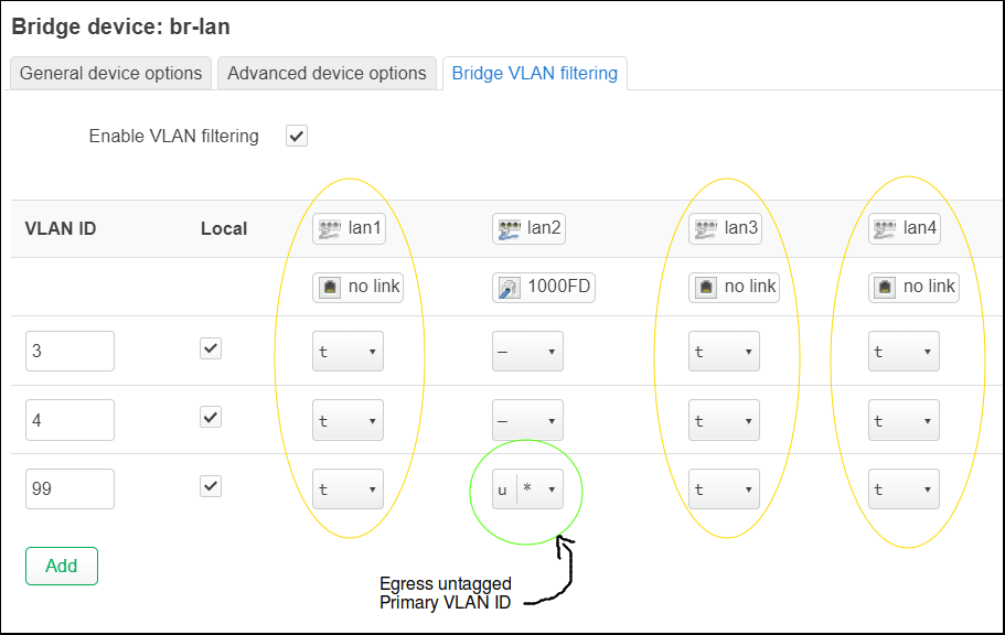
Mark all boxes “Egress tagged” for columns: lan1, lan3, and lan4.
For the lan2 column, we leave the rows vlan 3 and 4 empty, but mark the vlan 99 cell as both “Egress untagged” and “Primary VLAN ID”. This makes it the default VLAN (PVID), and any untagged packets will be assigned to VLAN 99.
CRITICAL NOTE: If you are using wired ethernet to connect to this router, be sure you are now plugged into the second physical ethernet port on the back of the router (lan2). After we apply these changes, the second port is the only one that will provide a management connection to your device.
Press “Save” for the device dialog. Do not press “Save & Apply” on the main page yet, we still need to change the LAN device to use the new VLAN.
Modify LAN interface from using ‘br-lan’ to untagged VLAN ‘br-lan.99’
From the “Interfaces” tab, press “Edit” on the LAN interface. The backing device will be shown as ‘br-lan’.
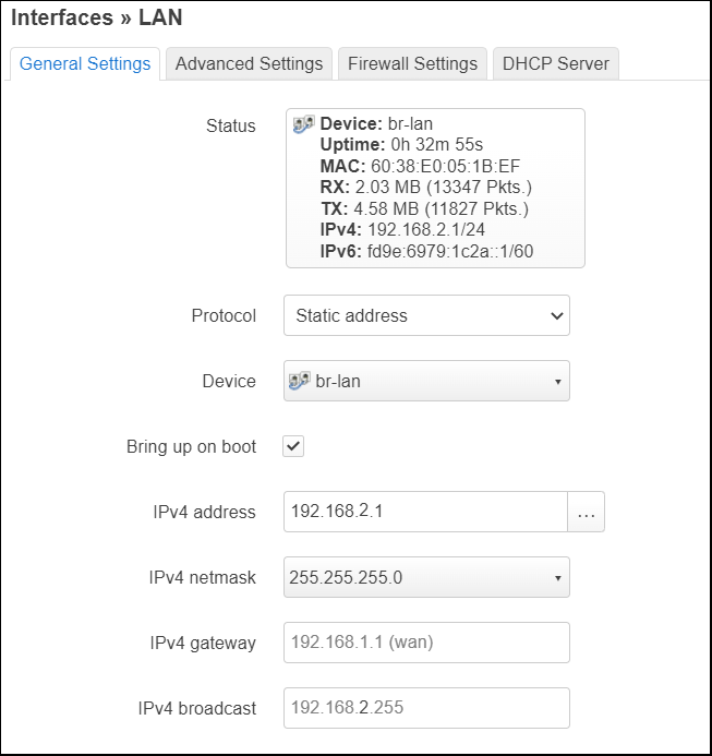
We want LAN to instead be using our untagged VLAN 99. Press on the Device selection pulldown and choose “Software VLAN: br-lan.99”. Press “Save” on the dialog.
Apply Changes
Press “Save & Apply” to have this batch of changes committed.
Changes seen from Luci
If you look at the ‘Devices’ tab now, there will be 3 new VLAN 802.1q devices: br-lan.3, br-lan.4, and br-lan.99
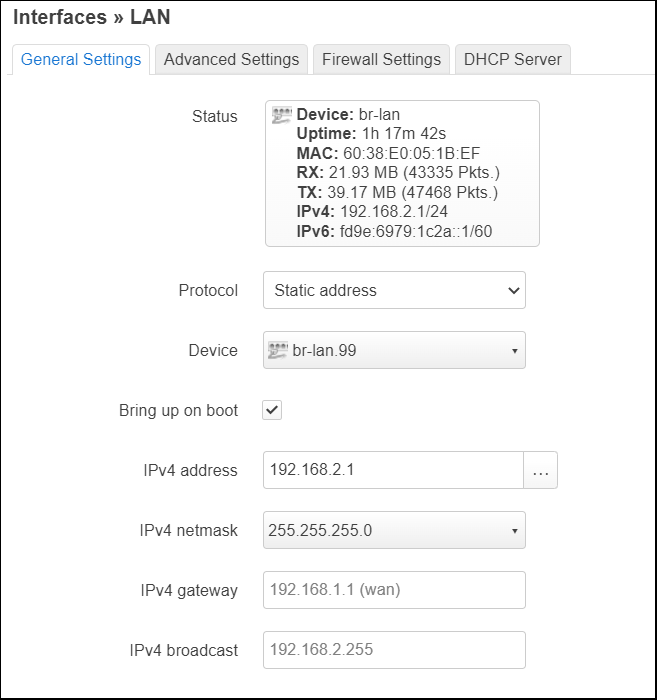
And from the ‘Interfaces’ tab, the LAN interface is now backed by ‘br-lan.99’
System Configuration changes
The network configuration will now have the LAN interface backed by ‘br-lan.99’, and three new ‘config bridge-vlan’ blocks for VLAN 3, 4, and 99 in /etc/config/network
config interface 'lan'
  ...
  option device 'br-lan.99' # was 'br-lan' before

 config bridge-vlan
       option device 'br-lan'
       option vlan '3'
       list ports 'lan1:t'
       list ports 'lan3:t'
       list ports 'lan4:t'

 config bridge-vlan
       option device 'br-lan'
       option vlan '4'
       list ports 'lan1:t'
       list ports 'lan3:t'
       list ports 'lan4:t'

 config bridge-vlan
       option device 'br-lan'
       option vlan '99'
       list ports 'lan1:t'
       list ports 'lan2:u*'
       list ports 'lan3:t'
       list ports 'lan4:t'
The OS level interfaces will now show an extra interface ‘br-lan.99@br-lan’, which has the IP address owned by ‘br-lan’ initially.
$ ip a | grep -E "^\d|inet "
...
12: br-lan: <BROADCAST,MULTICAST,UP,LOWER_UP> mtu 1500 qdisc noqueue state UP qlen 1000
13: br-lan.99@br-lan: <BROADCAST,MULTICAST,UP,LOWER_UP> mtu 1500 qdisc noqueue state UP qlen 1000
inet 192.168.2.1/24 brd 192.168.2.255 scope global br-lan.99
Add interfaces for IOT and Guest VLAN
VLAN 99 has already been assigned to the ‘LAN’ interface. Now we need to create interfaces for IOT=3 and GUEST=4.
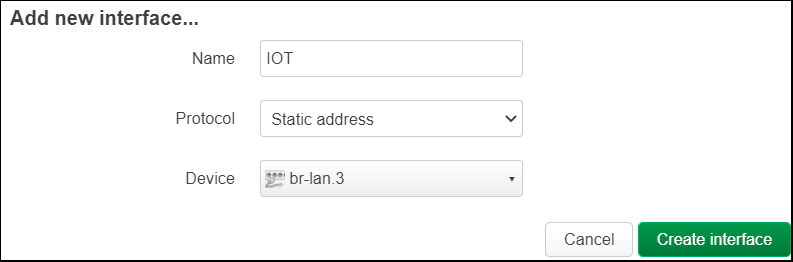
Add IOT VLAN interface
From “Interfaces”, press “Add new interface”.
In the dialog, use name=IOT, protocol=Static address, Device=br-lan.3. Press “Create interface”.
From “General Settings” tag, set IPv4 address=192.168.3.1, IPv4 netmask=255.255.255.0
Then select the “DHCP Server” tab, click on “Setup DHCP Server”, then press “Save”
Add GUEST VLAN interface
From “Interfaces”, press “Add new interface”.
In the dialog, use name=GUEST, protocol=Static address, Device=br-lan.4. Press “Create interface”.
From “General Settings” tag, set IPv4 address=192.168.4.1, IPv4 netmask=255.255.255.0
Then select the “DHCP Server” tab, click on “Setup DHCP Server”, then press “Save”
Apply Changes
Press “Save & Apply” to have this batch of changes committed.
Changes seen from Luci
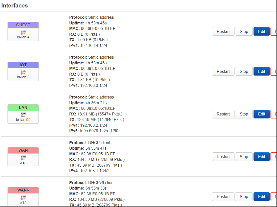
The “Interfaces” will show:
- IOT on br-lan.3 with IPv4: 192.168.3.1/24
- GUEST on br-lan.4 with IPv4: 192.168.4.1/24
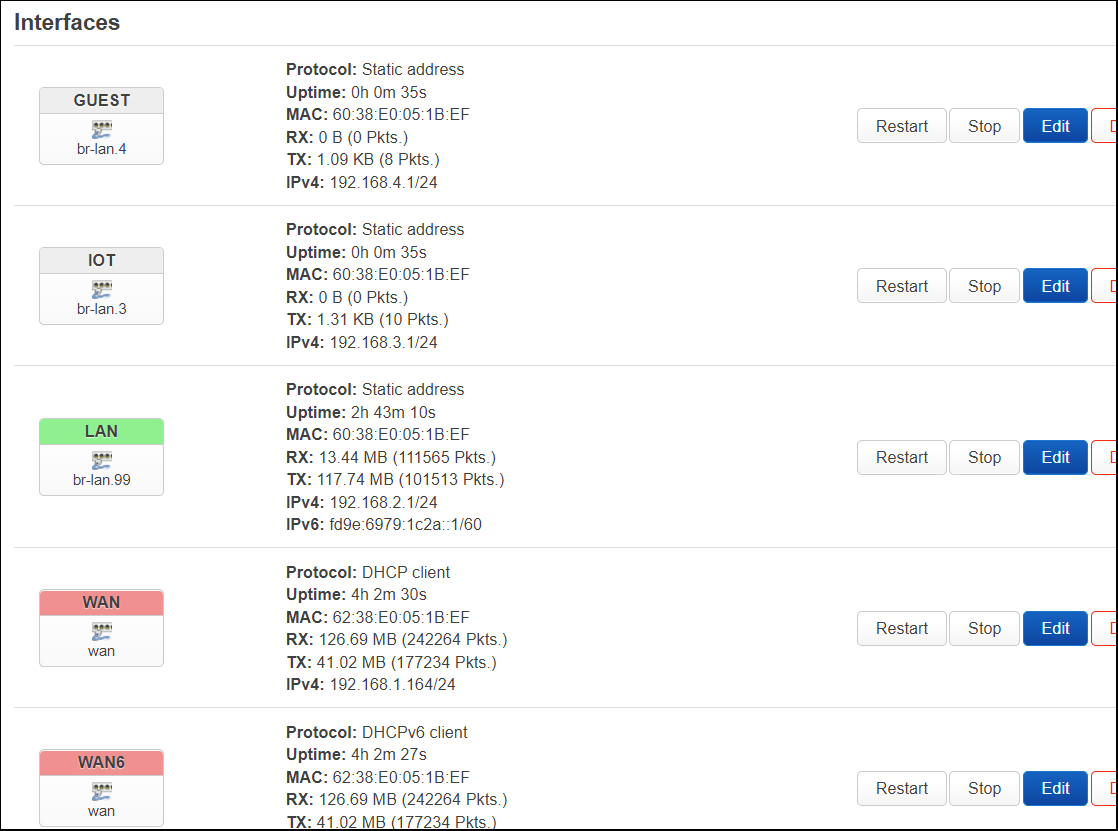
Notice that their boxes are light gray, that is because they have not been assigned a firewall zone. We will do this in the next section.
System Configuration changes
Two new ‘config interface’ have now been added to /etc/config/network
 config interface 'IOT'
       option proto 'static'
       option device 'br-lan.3'
       option ipaddr '192.168.3.1'
       option netmask '255.255.255.0'

 config interface 'GUEST'
       option proto 'static'
       option device 'br-lan.4'
       option ipaddr '192.168.4.1'
       option netmask '255.255.255.0'
And two new ‘config dhcp’ blocks have been added to /etc/config/dhcp
 config dhcp 'IOT'
       option interface 'IOT'
       option start '100'
       option limit '150'
       option leasetime '12h'

 config dhcp 'GUEST'
       option interface 'GUEST'
       option start '100'
       option limit '150'
       option leasetime '12h'
The OS level interfaces will now show two extra interfaces ‘br-lan.3@br-lan’ and ”br-lan.4@br-lan’.
$ ip a | grep -E "^\d|inet "
...
12: br-lan: <BROADCAST,MULTICAST,UP,LOWER_UP> mtu 1500 qdisc noqueue state UP qlen 1000
13: br-lan.99@br-lan: <BROADCAST,MULTICAST,UP,LOWER_UP> mtu 1500 qdisc noqueue state UP qlen 1000
    inet 192.168.2.1/24 brd 192.168.2.255 scope global br-lan.99
14: br-lan.4@br-lan: <BROADCAST,MULTICAST,UP,LOWER_UP> mtu 1500 qdisc noqueue state UP qlen 1000
    inet 192.168.4.1/24 brd 192.168.4.255 scope global br-lan.4
15: br-lan.3@br-lan: <BROADCAST,MULTICAST,UP,LOWER_UP> mtu 1500 qdisc noqueue state UP qlen 1000
    inet 192.168.3.1/24 brd 192.168.3.255 scope global br-lan.3
Add Firewall zones
In order to control communication between these networks, we need to configure zones and firewall rules.
Here is how we want to configure the firewall rules, as described by OneMarcFifty:
- LAN
- Can reach public internet
- Can manage connected devices in IOT network
- GuestZone
- Can reach public internet
- Can only communicate back to router via DNS and DHCP
- Cannot reach devices in any other network
- IOTZone
- Cannot reach public internet (i.e. cannot send data, images, or video back to manufacturer)
- Can only communicate back to router via DNS and DHCP
- Cannot reach devices in any other network
Add GuestZone and IOTZone
From the Network > Firewall page, scroll down to zones and create the two new zones.
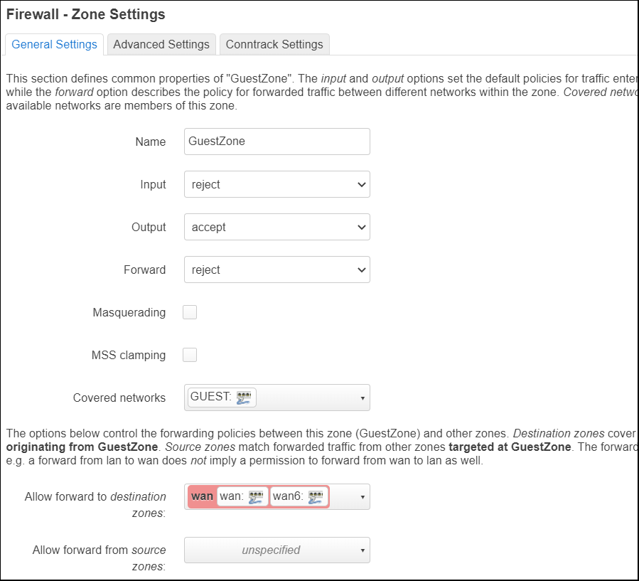
Add GuestZone
Press “Add”. Use name=”GuestZone”, Input=reject, then for ‘allow forward to destination zones’, select “wan”. Press “Save”
The Input=reject means that clients cannot communicate back to the router. But they can reach the wan zone for public internet access.
Add IOTZone
Press “Add”. Use name=”IOTZone”, Input=reject. Press “Save”
The Input=reject means that clients cannot communicate back to the router.
The fact that we did not add a forward to the wan zone means these IOT devices cannot reach the public internet.
Allow LAN users to reach IOT zone
Although we do not allow IOT devices to reach the public internet, we still need a way to manage these IOT devices. So we allow connectivity from the LAN to the IOT zone.
Press “Edit” on the lan zone. Under ‘allow forward to destination zones’, add “IOTZone” (now both wan and IOTZone are selected). Press “Save”.
Apply Changes
Press “Save & Apply” to have this batch of changes committed.
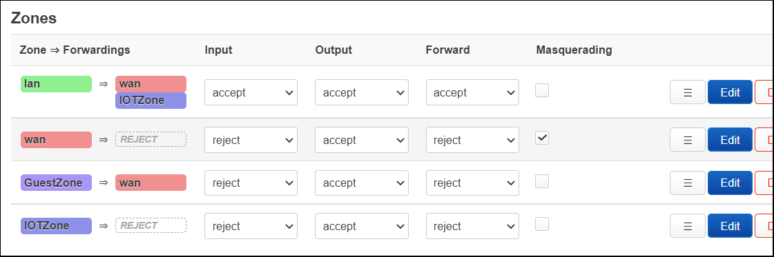
Changes seen from Luci
The zones will now show as below.
System Configuration changes
Two new ‘config zone’ and two new ‘config forwarding’ have now been added to /etc/config/firewall.
 config zone
       option name 'GuestZone'
       option output 'ACCEPT'
       option forward 'REJECT'
       option input 'REJECT'

 config forwarding
       option src 'GuestZone'
       option dest 'wan'

 config zone
       option name 'IOTZone'
       option output 'ACCEPT'
       option forward 'REJECT'
       option input 'REJECT'

 config forwarding
       option src 'lan'
       option dest 'IOTZone'
Add exceptions for DNS and DHCP requests
For both the GuestZone and IOTZone, we configured Input=reject. This blocks all traffic back to the router, but this is not our overall intention.
What we really want is to block all connection from the clients, except for DHCP and DNS. This will allow clients (mobile phone, laptop, IOT refrigerators, Amazon Alexa, etc.) to be handed an IP address via DHCP and do their DNS resolutions against the OpenWrt router.
We will also add ICMP, for troubleshooting network connectivity.
Add exception for GuestZone
Under Network > Firewall, go to the “Traffic Rules” tab. Scroll to the bottom of the page and press “Add”.
Set name=”Guest DHCP and DNS”, protocol=”TCP,UDP,ICMP”, source zone=”GuestZone”, destination zone=”Device (input)”, and destination ports=”53 67 68″. Press “Save”.
Add exception for IOTZone
Scroll to the bottom of the page and press “Add”.
Set name=”IOT DHCP and DNS”, protocol=”TCP,UDP,ICMP”, source zone=”IOTZone”, destination zone=”Device (input)”, and destination ports=”53 67 68″. Press “Save”.
Apply Changes
Press “Save & Apply” to have this batch of changes committed.
System Configuration changes
Two new ‘config rule’ have now been added to /etc/config/firewall.
 config rule
       option name 'Guest DHCP and DNS'
       option src 'GuestZone'
       option dest_port '53 67 68'
       option target 'ACCEPT'
       list proto 'tcp'
       list proto 'udp'
       list proto 'icmp'

 config rule
       option name 'IOT DHCP and DNS'
       list proto 'tcp'
       list proto 'udp'
       list proto 'icmp'
       option src 'IOTZone'
       option dest_port '53 67 68'
Set firewall zones on network interfaces
We need to go back to our network interfaces and apply the firewall zones just configured.
Under Network > Interfaces, press “Edit” on the GUEST interface. Select “Firewall Settings” tab and select “GuestZone”, then press “Save”.
Press “Edit” on the IOT interface. Select “Firewall Settings” tab and select “IOTZone”, then press “Save”.
Apply Changes
Press “Save & Apply” to have this batch of changes committed.
System Configuration changes
Two new lines ‘list network <INTERFACE>’ have been added to the ‘config zone’ blocks in /etc/config/firewall.
 config zone
       option name 'GuestZone'
       option output 'ACCEPT'
       option forward 'REJECT'
       option input 'REJECT'
       list network 'GUEST' # just added

 config zone
       option name 'IOTZone'
       option output 'ACCEPT'
       option forward 'REJECT'
       option input 'REJECT'
       list network 'IOT' # just added
Changes seen from Luci
From “Interfaces” the GUEST and IOT interfaces are no longer gray, they now match the color of the zones.
Add Wi-Fi interfaces for each network
This is a place where your router hardware will differ from my example. I’m using a LinkSys WRT 1900ACS v2 that has two wireless radios, one at 2.4Ghz and the other at 5Ghz. I’m going to configure the following:
- On the 5Ghz radio
- Wireless network with SSID=OpenWrtLAN
- Wireless network with SSID=OpenWrtIOT
- On the 2.4Ghz radio
- Wireless network with SSID=OpenWrtGuest
The important thing to understand is that the relationship between radio and wireless networks is not 1-1. I could have created all 3 wireless networks under a single radio.
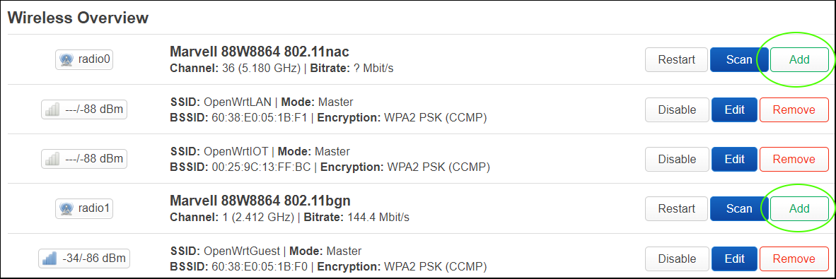
Pressing “Add” on a radio entry will create an additional wireless interface on it, with its own independent SSID, network, and password.
Setup OpenWrtLAN wireless interface
You can either press “Edit” on an existing wireless interface under the radio entry, or press “Add” on the radio entry to create a new interface.
Under the “General Setup” tab, use Mode=”Access Point”, ESSID=”OpenWrtLAN”, Network=”lan”
Under the “Wireless Security” tab, use Encryption=WPA2-PSK, cipher=auto, key=<password of your choosing>
The press “Save”.
Setup OpenWrtIOT wireless interface
You can either press “Edit” on an existing wireless interface under the radio entry, or press “Add” on the radio entry to create a new interface.
Under the “General Setup” tab, use Mode=”Access Point”, ESSID=”OpenWrtIOT”, Network=”IOT”
Under the “Wireless Security” tab, use Encryption=WPA2-PSK, cipher=auto, key=<password of your choosing>
The press “Save”.
Setup OpenWrtGuest wireless interface
You can either press “Edit” on an existing wireless interface under the radio entry, or press “Add” on the radio entry to create a new interface.
Under the “General Setup” tab, use Mode=”Access Point”, ESSID=”OpenWrtGuest”, Network=”GUEST”
Under the “Wireless Security” tab, use Encryption=WPA2-PSK, cipher=auto, key=<password of your choosing>
The press “Save”.
Enable all wireless interfaces
Press “Enable” on any wireless interfaces that say “Wireless is disabled”.
Smoke Test scenarios
The best way to prove out your work is to run through some basic tests.
IOT Network
- Connect to wireless ‘OpenWrtIOT’
- Verify that you receive an IP address in 192.168.3.0/24 (DHCP)
- Verify that you can do an nslookup to google.com (DNS)
- Verify that you CANNOT reach any public internet sites
- Verify that you can ping 192.168.3.1 (ICMP)
- Verify that you cannot pull up Luci on the router (https://192.168.3.1)
- Verify that you cannot pull up Luci on the upstream router (https://192.168.2.1)
- Verify that you can ping/call a service on peers inside your IOT network
- Verify that from a device on the LAN network you CAN ping/call a service in the IOT network
Guest Network
- Connect to wireless ‘OpenWrtGuest’
- Verify that you receive an IP address in 192.168.4.0/24 (DHCP)
- Verify that you can do an nslookup to google.com (DNS)
- Verify that you CAN reach public internet sites
- Verify that you can ping 192.168.4.1 (ICMP)
- Verify that you cannot pull up Luci on the router (https://192.168.4.1)
- Verify that you cannot pull up Luci on the upstream router (https://192.168.2.1)
- Verify that from a device on the LAN network you CANNOT ping/call a service in the Guest network
LAN Network
- Connect to wireless ‘OpenWrtLAN’
- Verify that you receive an IP address in 192.168.2.0/24 (DHCP)
- Verify that you can do an nslookup to google.com (DNS)
- Verify that you CAN reach public internet sites
- Verify that you can ping 192.168.2.1 (ICMP)
- Verify that you CAN pull up Luci on the router (https://192.168.2.1)
- Verify your IP address CANNOT be pinged from a device on the GUEST or IOT network
- Verify that you CAN ping an IP address on the IOT network
- Verify that you CANNOT ping an IP address on the GUEST network
REFERENCES
github fabianlee, diagram source
OneMarcFifty youtube, VLANs in OpenWrt 21
OneMarcFifty youtube, OpenWrt and Firewall for guest wifi
OpenWrt, DSA (distributed switch architecture) tutorial change from older swdist
Dev Odyssey youtube, How to Create a VLAN
spbkaizo gist, working VLAN bridge with DSA
cydergoth github, OpenWrt VLAN instructions
NOTES
Differences in configs between 19.x and 21.x
19.x has ‘config switch_vlan’, 21.x ‘config bridge-vlan’
for ‘config interface’, 19.x has ‘option ifname’, 21.x has ‘option device’
example /etc/config/network for LinkSys WRT1900ACv2 (Cobra)
config interface 'loopback'
        option device 'lo'
        option proto 'static'
        option ipaddr '127.0.0.1'
        option netmask '255.0.0.0'

config globals 'globals'
        option ula_prefix 'fd9e:6979:1c2a::/48'

config device
        option name 'br-lan'
        option type 'bridge'
        list ports 'lan1'
        list ports 'lan2'
        list ports 'lan3'
        list ports 'lan4'

config interface 'lan'
        option proto 'static'
        option ipaddr '192.168.2.1'
        option netmask '255.255.255.0'
        option ip6assign '60'
        option device 'br-lan.99'

config device
        option name 'wan'
        option macaddr '62:38:e0:05:1b:ef'

config interface 'wan'
        option device 'wan'
        option proto 'dhcp'

config interface 'wan6'
        option device 'wan'
        option proto 'dhcpv6'

config bridge-vlan
        option device 'br-lan'
        option vlan '3'
        list ports 'lan1:t'
        list ports 'lan3:t'
        list ports 'lan4:t'

config bridge-vlan
        option device 'br-lan'
        option vlan '4'
        list ports 'lan1:t'
        list ports 'lan3:t'
        list ports 'lan4:t'

config bridge-vlan
        option device 'br-lan'
        option vlan '99'
        list ports 'lan1:t'
        list ports 'lan2:u*'
        list ports 'lan3:t'
        list ports 'lan4:t'

config interface 'IOT'
        option proto 'static'
        option device 'br-lan.3'
        option ipaddr '192.168.3.1'
        option netmask '255.255.255.0'

config interface 'GUEST'
        option proto 'static'
        option device 'br-lan.4'
        option ipaddr '192.168.4.1'
        option netmask '255.255.255.0'
example /etc/config/wireless on LinkSys WRT1900ACv2 (Cobra)
config wifi-device 'radio0'
        option type 'mac80211'
        option path 'soc/soc:pcie/pci0000:00/0000:00:01.0/0000:01:00.0'
        option band '5g'
        option htmode 'VHT80'
        option country 'US'
        option cell_density '0'
        option channel '36'

config wifi-iface 'default_radio0'
        option device 'radio0'
        option network 'lan'
        option mode 'ap'
        option macaddr '60:38:e0:05:1b:f1'
        option ssid 'OpenWrtLAN'
        option encryption 'psk2'
        option key 'myfakepasswordLAN'

config wifi-device 'radio1'
        option type 'mac80211'
        option path 'soc/soc:pcie/pci0000:00/0000:00:02.0/0000:02:00.0'
        option channel '1'
        option band '2g'
        option htmode 'HT20'
        option country 'US'
        option cell_density '0'

config wifi-iface 'default_radio1'
        option device 'radio1'
        option mode 'ap'
        option macaddr '60:38:e0:05:1b:f0'
        option ssid 'OpenWrtGuest'
        option encryption 'psk2'
        option key 'myfakepasswordGuest'
        option network 'GUEST'

config wifi-iface 'wifinet2'
        option device 'radio0'
        option mode 'ap'
        option ssid 'OpenWrtIOT'
        option encryption 'psk2'
        option key 'myfakepasswordIOT'
        option network 'IOT'

config wifi-iface 'wifinet3'
        option device 'radio0'
        option mode 'ap'
        option ssid 'OpenWrt'
        option encryption 'none'
/etc/config/firewall differences on LinkSys WRT1900ACv2 (Cobra)
config zone
        option name 'GuestZone'
        option output 'ACCEPT'
        option forward 'REJECT'
        option input 'REJECT'
        list network 'GUEST'

config forwarding
        option src 'GuestZone'
        option dest 'wan'

config zone
        option name 'IOTZone'
        option output 'ACCEPT'
        option forward 'REJECT'
        option input 'REJECT'
        list network 'IOT'

config forwarding
        option src 'lan'
        option dest 'IOTZone'

config rule
        option name 'Guest DHCP and DNS'
        option src 'GuestZone'
        option dest_port '53 67 68'
        option target 'ACCEPT'
        list proto 'tcp'
        list proto 'udp'
        list proto 'icmp'

config rule
        option name 'IOT DHCP and DNS'
        list proto 'tcp'
        list proto 'udp'
        list proto 'icmp'
        option src 'IOTZone'
        option dest_port '53 67 68'
        option target 'ACCEPT'